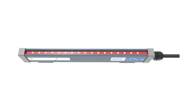
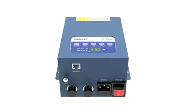
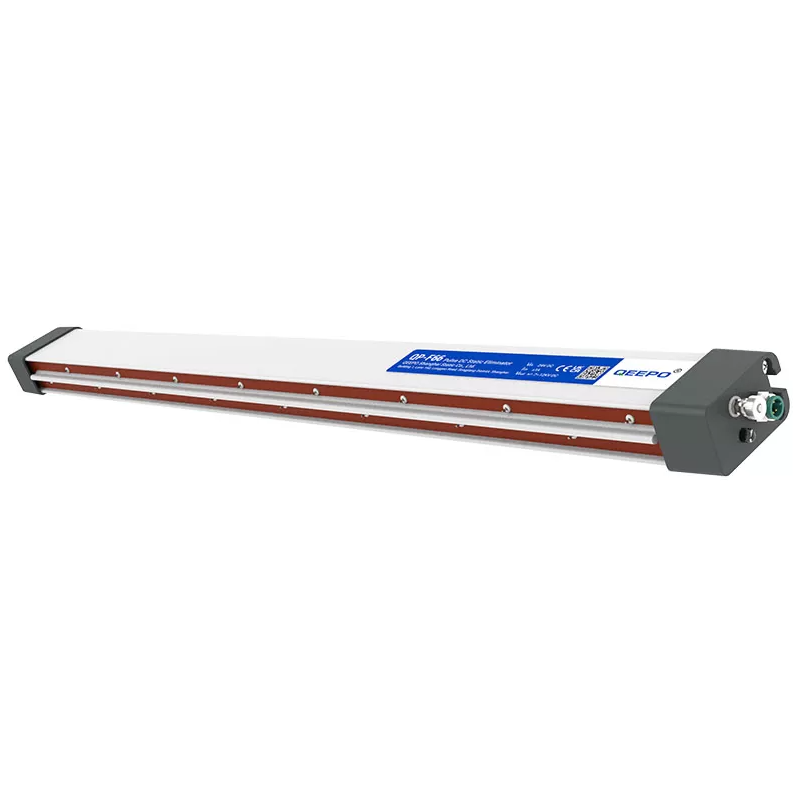
In certified cleanrooms, electrostatic discharge control is not optional — especially for electronics, medical devices, and precision assembly where latent ESD damage destroys yield without visible defects. An air ionizer fan (ionizing air blower) neutralizes static on insulators and isolated conductors that grounding alone cannot control. This guide explains how ionizing blowers support ANSI/ESD S20.20 programs, how an electrostatic fan differs from general airflow equipment, and what to verify for audit-ready deployment.
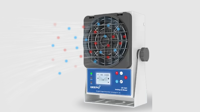
ANSI/ESD S20.20 requires a comprehensive ESD control program that addresses all charge generation mechanisms. Grounding is the foundation — but it only works for conductors and dissipative materials that have a physical connection to ground. Insulators do not allow charge to flow and cannot be grounded in any meaningful sense.
| Surface Type | Grounding Effectiveness | Ionization Requirement |
|---|---|---|
| ESD-protected operator | High — wrist strap connects to ground | Supplementary — for insulative materials the operator handles |
| ESD mat on workbench | High — dissipative surface connects to ground | Supplementary — items placed on the mat may not contact it |
| Plastic tray or carrier | None — insulator holds charge indefinitely | Essential — only ionization can neutralize this surface |
| Plastic bag or film | None — charge builds during peeling and handling | Essential — high charge generation event |
| Unpackaged PCB with floating nodes | Partial — board ground may not contact handler ground | Critical — floating conductor can accumulate charge |
Peeling protective films from assemblies or screens — highly charge-generative event
Conveyor belt movement — belt surface accumulates charge from contact and separation
Operator garments — even ESD-compliant garments generate charge during movement
Non-ESD containers and work holders used for convenience — common compliance gap
Wiping and cleaning operations — even lint-free wipes on surfaces generate charge
An air ionizer fan uses high-voltage energized emitter needles to ionize the air molecules in close proximity to the emitter tips. The corona discharge at each needle tip produces both positive ions (from removal of electrons) and negative ions (from electron attachment to neutral air molecules). These ions are then transported away from the emitter by the blower's airflow and carried to the charged target surface.
| Stage | What Happens | Performance Parameter |
|---|---|---|
| Ion generation | High voltage at emitter tips creates positive and negative ions | Emitter condition directly affects ion output |
| Ion transport | Blower airflow carries ions to the target surface | Airflow volume, direction, and distance to target |
| Charge neutralization | Ions of opposite polarity to the surface charge migrate to and neutralize it | Decay time — how quickly charge drops to a safe level |
| Balance | Excess ions of either polarity are avoided | Offset voltage — how close to zero the residual charge is |
Offset voltage (balance): a poorly balanced ionizer may neutralize charge but leave the surface at a residual voltage — typically required to be within ±35V for sensitive device handling
Decay time: the time required to reduce a known initial charge (typically 1,000V or 100V) to a safe level — shorter decay time means faster protection
Coverage distance: the working distance from the blower face at which the stated performance is achieved — verify this matches your actual workstation geometry
ANSI/ESD S20.20 and the associated IEC 61340-5-1 standard require documented ionizer verification at defined intervals. The verification measurements — offset voltage and decay time — must meet defined limits. An ionizer that produces good initial readings but drifts quickly between maintenance events creates a compliance gap.
| Process Zone | Why Ionization Is Needed | Recommended Placement |
|---|---|---|
| Assembly workstation | Operator handles insulators; static-sensitive devices unpacked | Overhead mount or bench-edge mount aimed at the work area |
| Packaging and labeling | Film peeling and label application generate significant charge | Positioned to cover the peel and label application point |
| Inspection bench | Devices placed on non-ESD surfaces; visual inspection of bare assemblies | Positioned to cover the inspection surface from the side or overhead |
| Conveyor transfer point | Charge builds on belt; transferred to products at transition | Mounted above or beside the transfer point; aimed at product surface |
| PCB load/unload | Board removed from or inserted into fixtures | Positioned to cover the fixture and board during the handling event |
Distance to target: most bench-top ionizing blowers are specified for working distances of 30–90 cm — verify the specification matches your actual bench-to-target distance
Airflow angle: direct airflow toward the highest charge-generation point in the operation; avoid aiming directly at sensitive components that could be physically displaced by the airflow
Avoiding dead zones: ensure the blower's coverage reaches the actual product handling zone — obstructions like stands, fixtures, and equipment can shadow parts of the workstation from ion coverage
Airflow velocity: must be sufficient to transport ions to the target but low enough not to disturb lightweight components or assemblies
Ionization is not a substitute for the other elements of an ESD control program — it is an addition that addresses the residual static risk on insulators.
Grounding: all conductors and personnel must still be grounded
ESD mats and surfaces: dissipative surfaces at all workstations
Garments and footwear: ESD-compliant attire throughout the EPA (ESD Protected Area)
ESD packaging: components stored and transported in ESD-protected packaging
Ionization: neutralizes charge on insulators and isolated conductors that the above controls cannot address
An ionizer in a certified ESD program is not verified once and assumed to be performing. ANSI/ESD S20.20 requires periodic verification with documented results. Auditors specifically look for:
| Documentation Element | What It Demonstrates |
|---|---|
| Initial performance qualification | The blower met the required offset voltage and decay time when installed |
| Periodic verification records | Performance has been measured at defined intervals and results recorded |
| Maintenance records | Emitter cleaning and any repairs have been performed and documented |
| Out-of-specification events | Any failures were recorded, investigated, and corrected before resuming production |
| Calibration traceability | The test equipment used for verification is calibrated to a traceable standard |
Offset voltage measurement: using a calibrated charged plate monitor (CPM), measure the steady-state voltage the ionizer delivers to the test plate — acceptance limit is typically ±35V for most ESDS (electrostatic discharge sensitive device) handling
Decay time measurement: using a CPM, measure the time required to reduce a 1,000V charge on the test plate to 100V — acceptance limit varies by standard and application; 2–20 seconds is common for bench-top work
Both measurements are taken at the specified working distance — any increase in working distance should trigger re-verification
| Maintenance Task | Frequency | Why It Matters |
|---|---|---|
| Emitter needle cleaning | Monthly or per manufacturer guidance | Contaminated emitters produce fewer ions; balance drifts |
| Filter cleaning or replacement (if applicable) | Per manufacturer schedule | Blocked filter reduces airflow; reduces ion delivery to target |
| Performance verification | Per S20.20 compliance schedule; at minimum annually | Confirms emitters and balance circuits are functioning correctly |
| Alarm indicator check | At each shift or daily | Confirms the unit will alert if balance or ionization fails |
| Parameter | What to Define | Target for Sensitive Electronics |
|---|---|---|
| Offset voltage (balance) | Residual voltage on a test plate at working distance | Within ±15–35V depending on device sensitivity |
| Decay time | 1,000V to 100V at specified working distance | Under 5 seconds for fast-paced assembly; under 2 seconds for highly sensitive devices |
| Working distance | Distance from blower face to coverage zone | Confirm matches your physical workstation geometry |
| Airflow volume | Air velocity and volume at working distance | Sufficient to transport ions without displacing lightweight components |
| Noise level | dB(A) at operating airflow | Cleanroom environments may have strict noise limits |
| Ozone generation | ppm ozone at operating conditions | Must be within OSHA limits; near-zero preferred for occupied cleanrooms |
| Emitter life | Rated hours or cleaning interval | Longer emitter life reduces maintenance frequency |
Particle emission: the ionizer must not generate particles that would violate the cleanroom classification
Materials compatibility: all external surfaces should withstand IPA cleaning and standard cleanroom disinfectants
Easy-clean design: smooth surfaces; no particle-trapping features; accessible emitters for cleaning
Spares: stock replacement emitter assemblies and any consumable filters
Training: operators should understand the daily alarm check procedure and when to call for maintenance
Standardized work instructions: define the verification frequency, test method, and acceptance limits in a written SOP that references ANSI/ESD S20.20
A certified ESD program is only as strong as its control of insulators and isolated conductors. An air ionizer fan provides a measurable, repeatable way to reduce electrostatic charge in critical process zones, supporting ANSI/ESD S20.20 compliance and protecting product yield from the hidden cost of latent ESD damage. When selecting an electrostatic fan solution, focus on offset voltage performance, decay time, balance stability, maintainability, and the verification discipline that keeps the program audit-ready.
Q1: What does an air ionizer fan do in a cleanroom ESD program?
An air ionizer fan generates positive and negative ions from high-voltage emitters and transports them to charged surfaces using airflow. When the ions reach a charged insulator or isolated conductor, they neutralize the accumulated static charge. This addresses the one category of ESD risk that grounding cannot control — surfaces that do not allow charge to flow.
Q2: How is an electrostatic fan different from a standard cleanroom fan?
A standard fan moves air for temperature, humidity, or particle control but has no effect on static charge. An electrostatic fan (ionizing air blower) includes high-voltage emitter needles, a balance control circuit, and a verification system to confirm that the ion output is balanced between positive and negative. The performance is measured in terms of offset voltage and charge decay time — neither of which a standard fan can influence.
Q3: How do I verify that my ionizing air blower is functioning correctly?
Use a calibrated charged plate monitor (CPM) to measure offset voltage and decay time at the actual working distance. Offset voltage should be within ±35V (or tighter for sensitive devices); decay time should meet the limit defined in your ESD control plan. Perform this verification at the interval required by your ANSI/ESD S20.20 compliance schedule and document all results with the date, operator, and equipment calibration status.
Q4: Where should ionizing blowers be installed in a cleanroom or EPA?
Position them to cover the zones where insulators are handled or where significant charge generation occurs — film peeling, tray handling, packaging, inspection benches, and conveyor transfer points. The blower face should be at the specified working distance from the target surface, aimed to direct airflow at the product handling zone. Ensure there are no obstructions that would create unprotected shadow zones in the coverage area.
Q5: What maintenance does an air ionizer fan require to maintain compliance?
Emitter needles must be cleaned regularly — contamination reduces ion output and causes balance drift. Filters, if present, must be cleaned or replaced per the manufacturer's schedule to maintain adequate airflow. Performance verification (offset voltage and decay time measurements) must be conducted at defined intervals and results documented. Alarm indicators should be checked daily or per shift to confirm the unit would alert if ionization or balance failed.

 +86-17717352246
  andy@qeepo.cn
 English
  日本語
日本語  한국어
한국어  français
  Español
  русский
  português
  العربية
  tiếng việt
  ไทย
ไทย  Polska